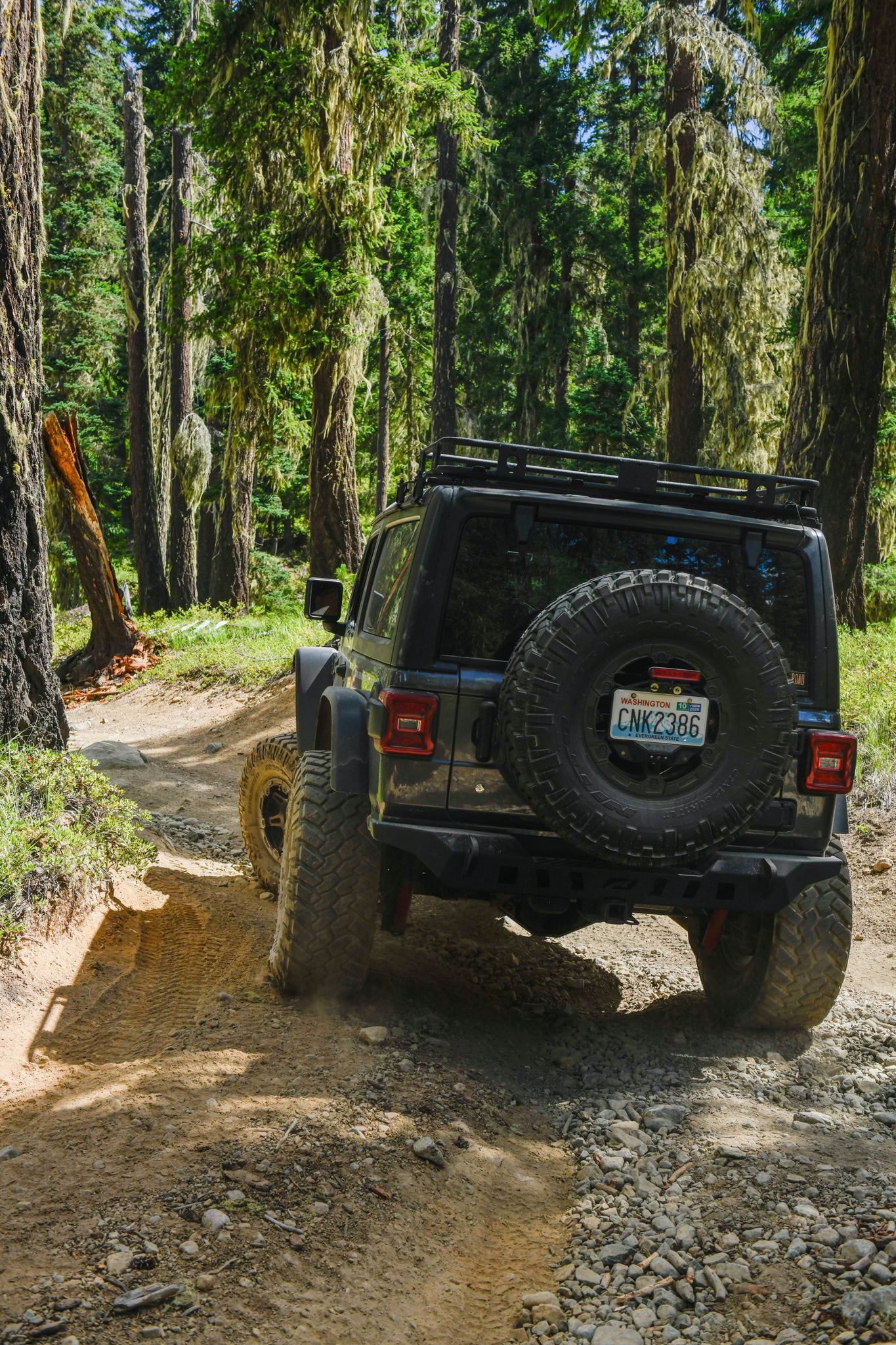
Retrofitting a Factory eLSD into a WK2 Grand Cherokee
Adding Quadra-Drive II's electronic limited-slip differential to a 2015 Grand Cherokee Limited using a 2018 Trailhawk donor. The mechanical swap was the easy part. Almost everything I believed about the electronics turned out to be wrong.
One of the more interesting things about modern 4x4s is how often the hardware you want already exists somewhere else in the same platform.
That was the case with our Grand Cherokee. It’s a 2015 Limited with Quadra-Trac II, so it left the factory with an open rear differential. The electronically controlled limited-slip that comes with Quadra-Drive II was never fitted.
We had a complete 2018 Trailhawk parts car sitting there with one in it.
The differential swap itself was straightforward, and afterward the Jeep drove fine in QT2 mode. The real question was the other half of the job: the control module, a harness that doesn’t exist in this car, and convincing the vehicle that a feature it was never built with is now present.
That part went better than expected. But not for the reasons I assumed going in, and almost everything I believed at the start turned out to be wrong.
Those corrections are the useful part of this write-up, so that’s most of what follows.
What the eLSD actually does
An open differential lets the rear wheels turn at different speeds, which is what you want in a corner. The cost is that torque follows the path of least resistance. Lift a rear tire and that’s where your engine output goes.
The eLSD adds a clutch pack that progressively couples the two rear axle shafts. A ball-ramp actuator, driven by a small electric motor, applies clamping force on command.
Rather than waiting for a wheel to spin and then trapping it with the brakes, the vehicle can send torque across the axle before the slip develops.
Off-road that matters on crossed-up climbs, loose rock, and anywhere a rear tire goes light. You keep moving with less wheelspin and less intervention from brake-based traction control — which is hard on brakes and slow to react.
The part number settles more than fitment
The module is P05150734AC, a Bosch unit, and it covers 2014–2018 Grand Cherokee. Our 2015 is in range. The supersession chain runs AB → AC → AD → AE, and AE covers 2014 through 2026 across both Grand Cherokee and Durango.
That fitment range does more than confirm the part fits. It quietly answers the question everyone asks first.
The VIN programming myth
Search this swap and you’ll be told the module has to be VIN-married by a dealer with wiTECH. I believed that going in. It’s the main thing that makes people abandon the idea.
When I actually traced the sourcing, every instance of that claim led back to one parts retailer’s SEO content — the same site cited repeatedly across separate searches, wearing different hats. It’s marketing copy from a vendor with a commercial interest in the job sounding dealer-only.
The service manual says something different. In the eLSD module description, under inputs:
Inputs include: Vehicle speed, Wheel speed, Terrain mode ELSD position sensor, and VIN, odometer for diagnostics.
VIN is an input the module receives over CAN. Not a stored marriage. A used module reads whatever VIN the car broadcasts at it.
The part number argues the same thing structurally. One SKU spanning thirteen model years and two vehicle lines cannot be VIN-locked at the factory — it only works if the module takes its configuration from the vehicle at runtime.
FCA does VIN-lock modules, but the list is confined to the immobilizer chain, emissions, and odometer-legal parts: PCM, TCM, BCM, RF Hub, WCM, IPC, some ABS. A differential controller is none of those. Nobody steals a Jeep by swapping the rear diff brain.
Two different things get conflated here. VIN marriage means the module refuses to work unless its stored VIN matches the car. Proxi configuration means the car has to be told the feature exists.
This job needs the second one. Only the first would have required a dealer.
The diagram I started with was wrong in every particular
I began with a 2011 WK2 eLSD diagram, on the reasonable assumption that WK2 is WK2.
The WK2 got a significant electrical revision at the 2014 refresh. Once I had the correct 2016 service manual and compared them, the 2011 diagram was wrong about all six circuit IDs, all six wire colors, and the fuse ratings.
Not “mostly right with some drift.” Wrong in every field.
| 2011 diagram | 2016 manual (correct) | |
|---|---|---|
| Circuit IDs | A26, A803, F943, D11, D12, Z216 | A206, A918, F946, D431, D432, Z917 |
| Colors | RED, RED/BLK, PNK/LT GRN, WHT/LT BLU, WHT/BRN, BLK | RD, PK/BK, RD/LG, DG/WT, YL, BK |
| Run/Start fuse | 20A | 10A |
| Diff connector | separate 2-pin + 8-pin | one 10-cavity |
The connector architecture changed too. If you’re doing this on a 2014-or-later car, a pre-refresh diagram will actively lie to you.
The diff side, interestingly, did not change. The dark-green-tracer family on the differential harness matches the old table exactly. Only the module side moved.
What the module actually needs
Three connectors. Only one of them touches the battery.
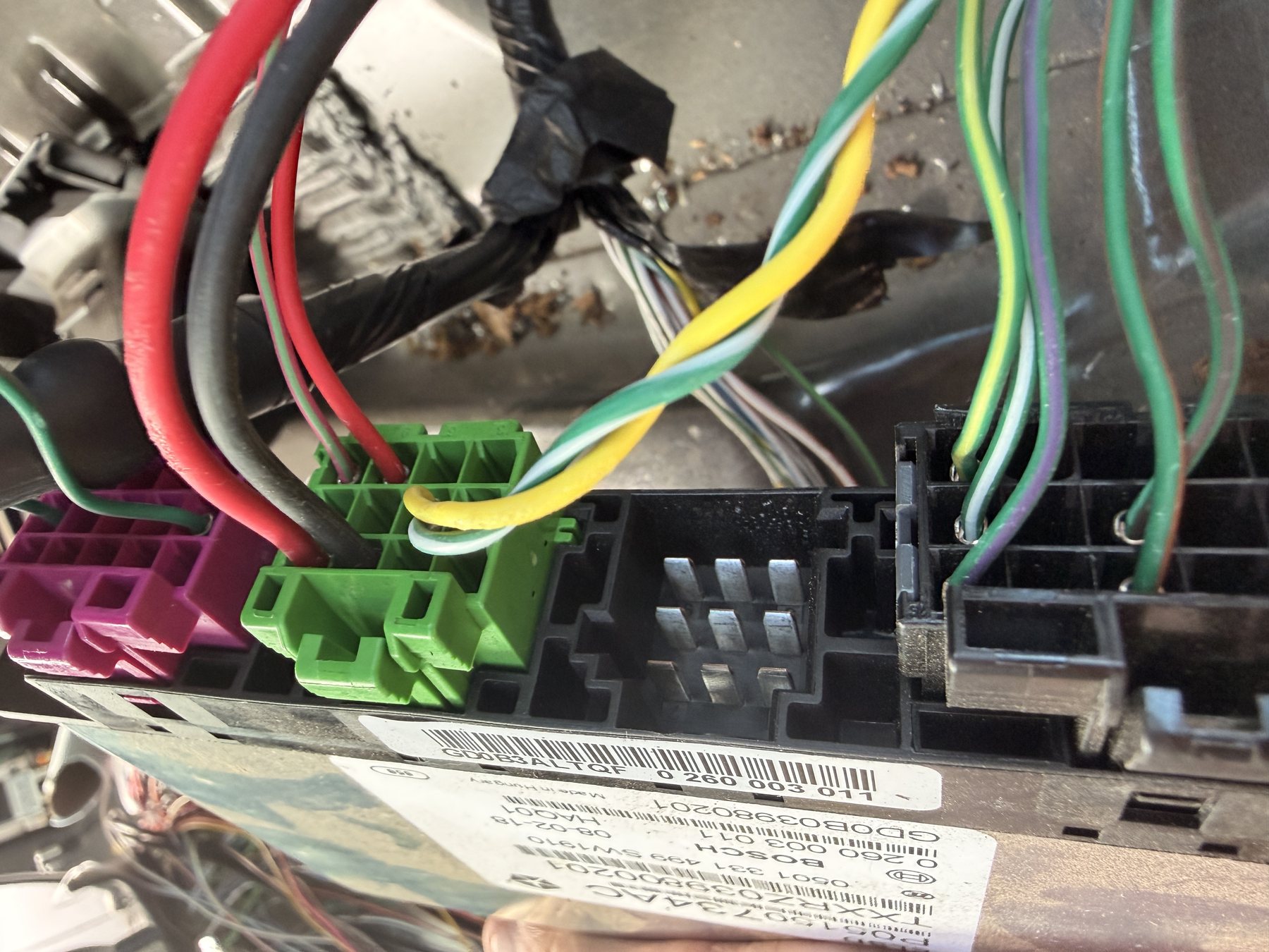
C3, the green one, is the whole electrical job:
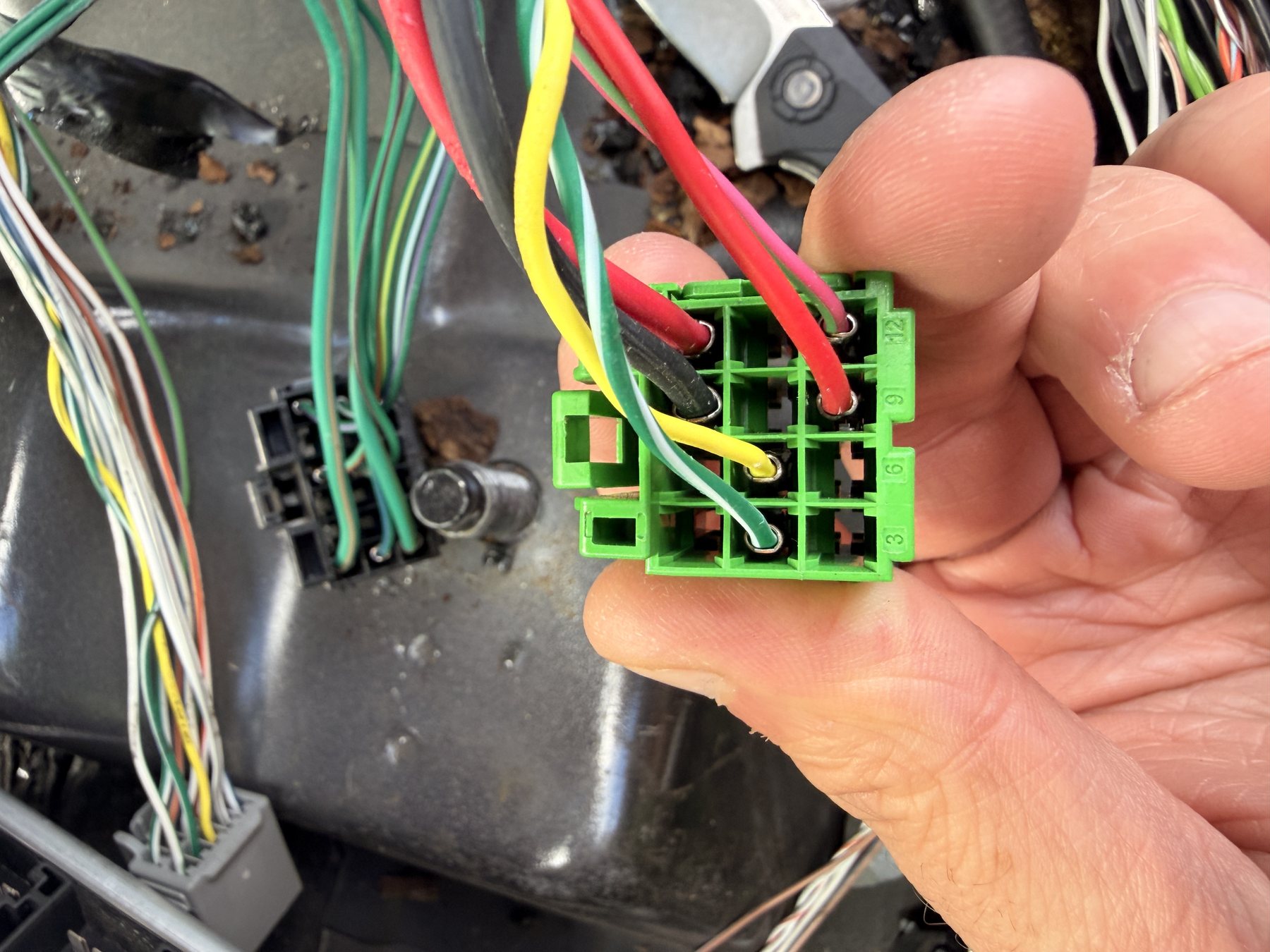
| C3 pin | Function | Circuit | Gauge | Color | Fuse |
|---|---|---|---|---|---|
| 9 | Fused B(+) | A206 | 18 | PK/BK | PDC 50 — 20A |
| 10 | Fused B(+) | A918 | 14 | RD | PDC 34 — 30A |
| 12 | Run/Start control | F946 | 20 | RD/LG | PDC 77 — 10A |
| 2 | CAN C (+) | D431 | 20 | DG/WT | — |
| 5 | CAN C (−) | D432 | 20 | YL | — |
| 7 | Ground | Z917 | 14 | BK | — |
Two always-hot feeds, one switched, a ground, and a CAN pair. That’s it.
Worth noting: factory gauge on the 30A leg is 14 AWG, not the 10 or 12 I’d assumed. The run is short and the duty cycle is low — the actuator motor only draws when it’s clamping.
Everything on the differential side is an output or a sensor return. Position sensors, temperature sensor, motor drive. Put battery voltage on any of those and you will destroy the hall sensors and possibly the module.
Only C3 sees B(+). Fuse at the source, and never at the diff end.
Ten dark green wires
This is the part I’d most want somebody else to read.
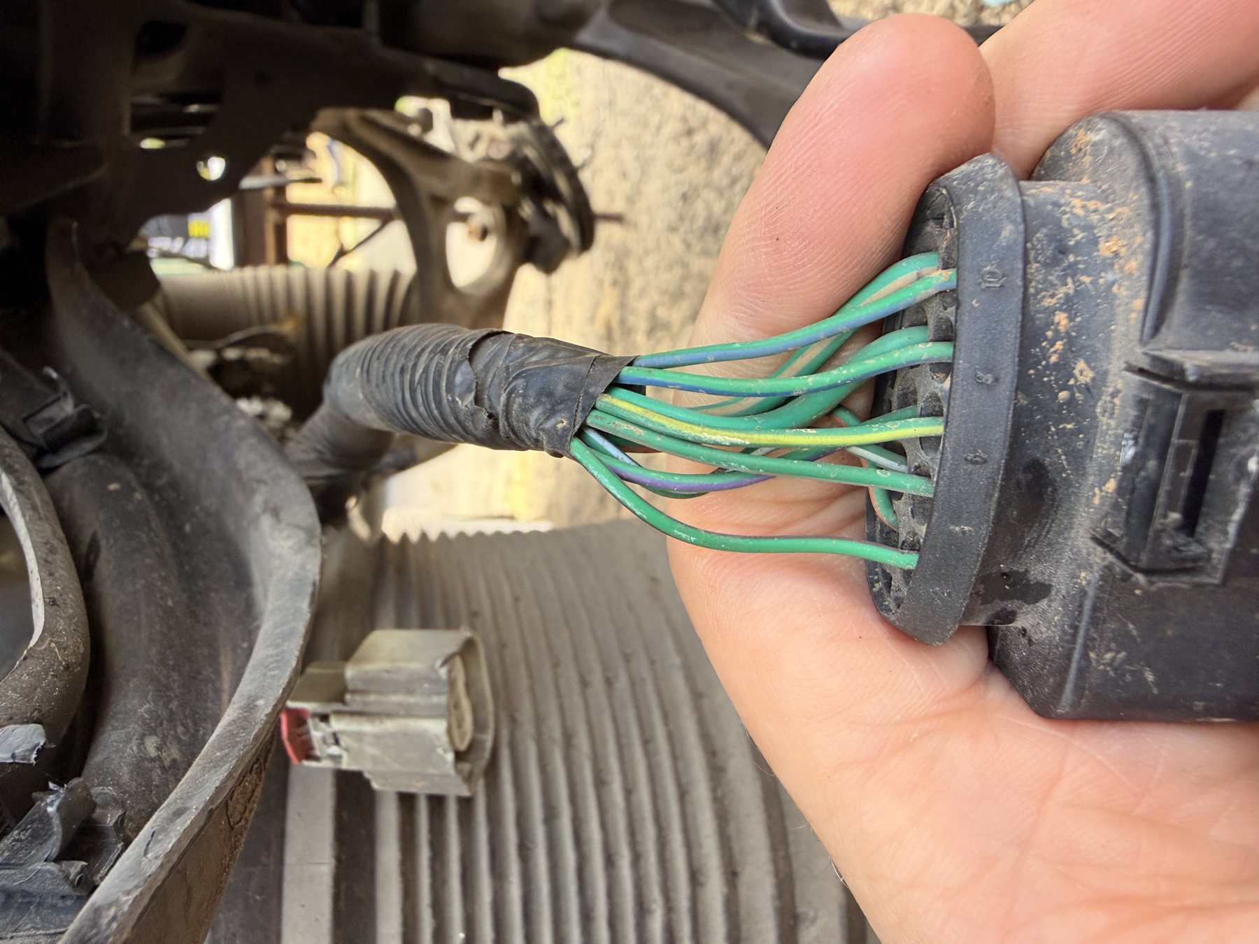
Every conductor on the differential side is dark green. All ten of them. The only thing separating one from another is the tracer stripe:
| Module pin | Color | Function |
|---|---|---|
| C1-1 | DK GRN/TAN | Motor N out |
| C1-3 | DK GRN/LT GRN | Motor out in |
| C1-2 | DK GRN/DK BLU | Clamp motor N out |
| C4-14 | DK GRN/LT BLU | Clamp motor out in |
| C1-10 | DK GRN/ORG | Temp sensor signal |
| C1-11 | DK GRN/BRN | Temp sensor return |
| C1-16 | DK GRN/VIO | Position sense feed |
| C1-18 | DK GRN/YEL | Position sense return |
| C1-17 | DK GRN/WHT | SIG1 |
| C4-3 | DK GRN/GRY | SIG2 |
Dark blue. Violet. Grey. On a dark green base, in a wheel well, under a work light.
I’m colorblind. I crossed three of them — the dark blue, the violet and the grey.
The symptom is the useful part
Here’s what made it interesting to diagnose: the CAN wiring was fine.
The module powered up, joined the bus, and enumerated in the scan tool exactly as it should. By every network-level measure the retrofit had worked.
Every single circuit read open or short.
That combination is a precise diagnostic signature, and it’s worth committing to memory:
Module present on the bus, but all circuits faulted → the problem is downstream of the module on C1/C4, not on the network. Stop testing the bus. Go back to the differential harness.
If the module hadn’t appeared at all, I’d have been hunting CAN and power. Because it appeared and reported nothing but faults, the fault had to be on the side that carries no data — the actuator and sensor circuits.
The fix is to stop using your eyes
Every one of those ten conductors has an electrical signature. Meter across pairs at the diff connector, module disconnected, and they identify themselves:
| Reading between two cavities | What it is |
|---|---|
| 1–5 Ω | Motor winding — the main actuator pair |
| Low ohms, second pair | Clamp motor |
| 2–10 kΩ at room temperature | Temp sensor. Warm the housing and watch it move. |
| Open, won’t read passively | Hall sensors — they need power |
That’s a positive identification of four circuit groups without looking at a single stripe. Build the continuity map from those readings, label physically as you go, and the colours become a cross-check rather than the source of truth.
The two that matter most are C1-1 and C1-3 — the main motor pair, tan tracer versus light green. Reverse those and the ball-ramp actuator drives backward. Map and tag those two first, before anything else gets cut.
And one more, on the bus side
Not what caught me, but it’s the same shape of trap and it’s sitting right there.
The DTCM is a valid CAN C tap point, but its colours are inverted relative to the eLSD:
| CAN C (+) | CAN C (−) | |
|---|---|---|
| eLSD (D431 / D432) | DG/WT — dark green, white tracer | YL — yellow |
| DTCM (D301 / D302) | WT — solid white | DG — solid dark green |
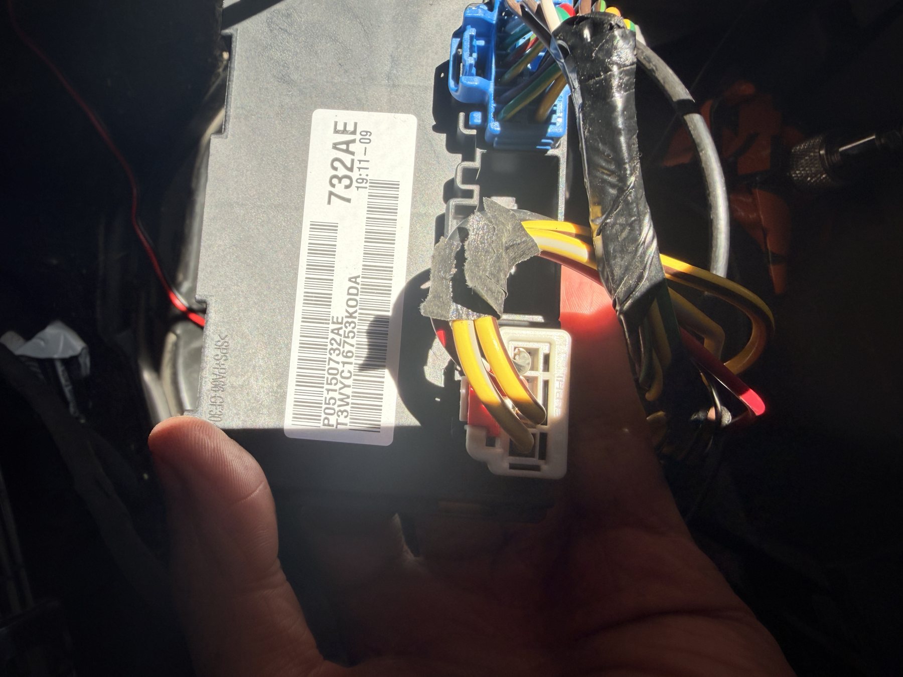
Splice dark green to dark green — exactly what instinct says — and you have reversed CAN polarity. Different legs off the star, different circuit IDs.
Check it with a meter instead: across the pair, key off, CAN C reads about 60 Ω, being two 120 Ω terminators in parallel. Kilohms means you’re on the wrong bus entirely.
The ignition feed is not the cigar lighter
The obvious source for a switched 12V is an accessory outlet. It doesn’t work here, and the reason is worth knowing.
The manual is explicit that power outlets marked with a key symbol are live in ON or ACC, and outlets marked with a battery symbol are live at all times.
Neither is what the module wants. The eLSD’s switched feed is a RUN-START circuit:
- An ON/ACC outlet drops during crank. The module would reboot every single start.
- An always-hot outlet never sleeps, so the module never powers down.
The correct source is PDC fuse F77, 10A, which feeds the drivetrain control module and the front axle disconnect. The same fuse, same circuit ID, and same wire color that the factory runs to the eLSD on cars that came with it. It’s already populated on a car without the option.
Tap F77 with an add-a-circuit and you’ve replicated the factory arrangement exactly.
I’d also planned a relay for this leg and it turned out to be unnecessary. Pin 12 is a 20 AWG enable input, not a power feed — the real current arrives on pins 9 and 10. The factory hangs three modules off F77 with no intermediate relay.
The harness
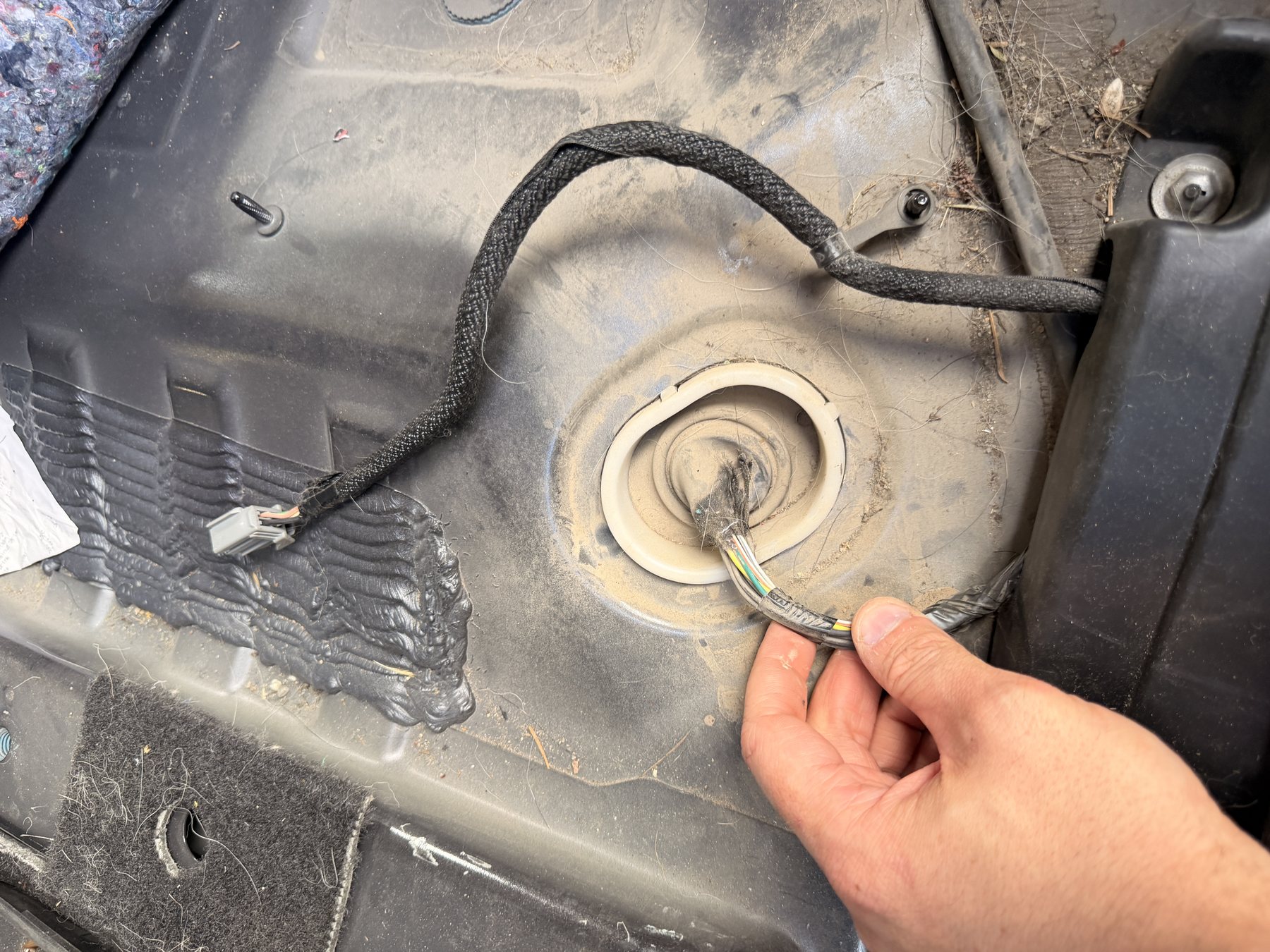
The differential-side branch is integrated into the underbody loom. Extracting it intact means pulling the loom apart, which is not a reasonable use of a weekend.
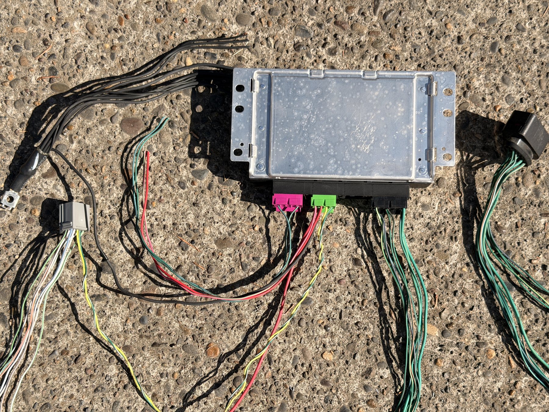
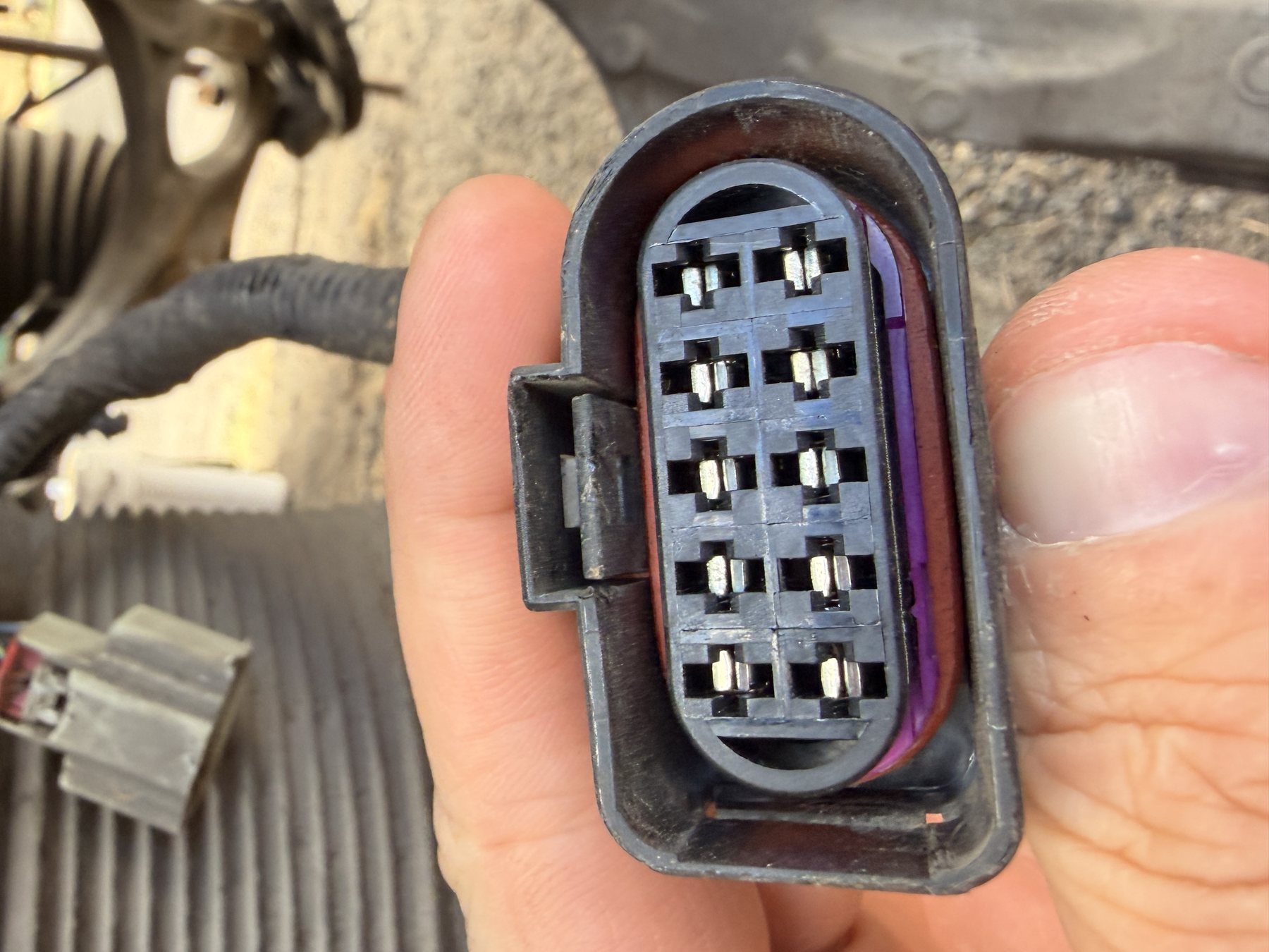
So: cut both factory connectors — module side and differential side — leaving roughly a foot of original wire on each. That keeps the factory terminals, the factory housings, and enough original color-coded wire to identify every conductor at both ends. Everything between is new. The 2014 refresh consolidated the older two-connector arrangement into the single 10-cavity housing shown above.
Before cutting anything, continuity-map the donor harness end to end and photograph every connector face with the cavities visible. Once it’s out of the car and the parts car is gone, that information doesn’t exist anywhere.
Where I actually put it
The factory location is under the left side of the rear seat. That is where a car built with the option carries it, and it is what the service manual specifies.
I didn’t use it.
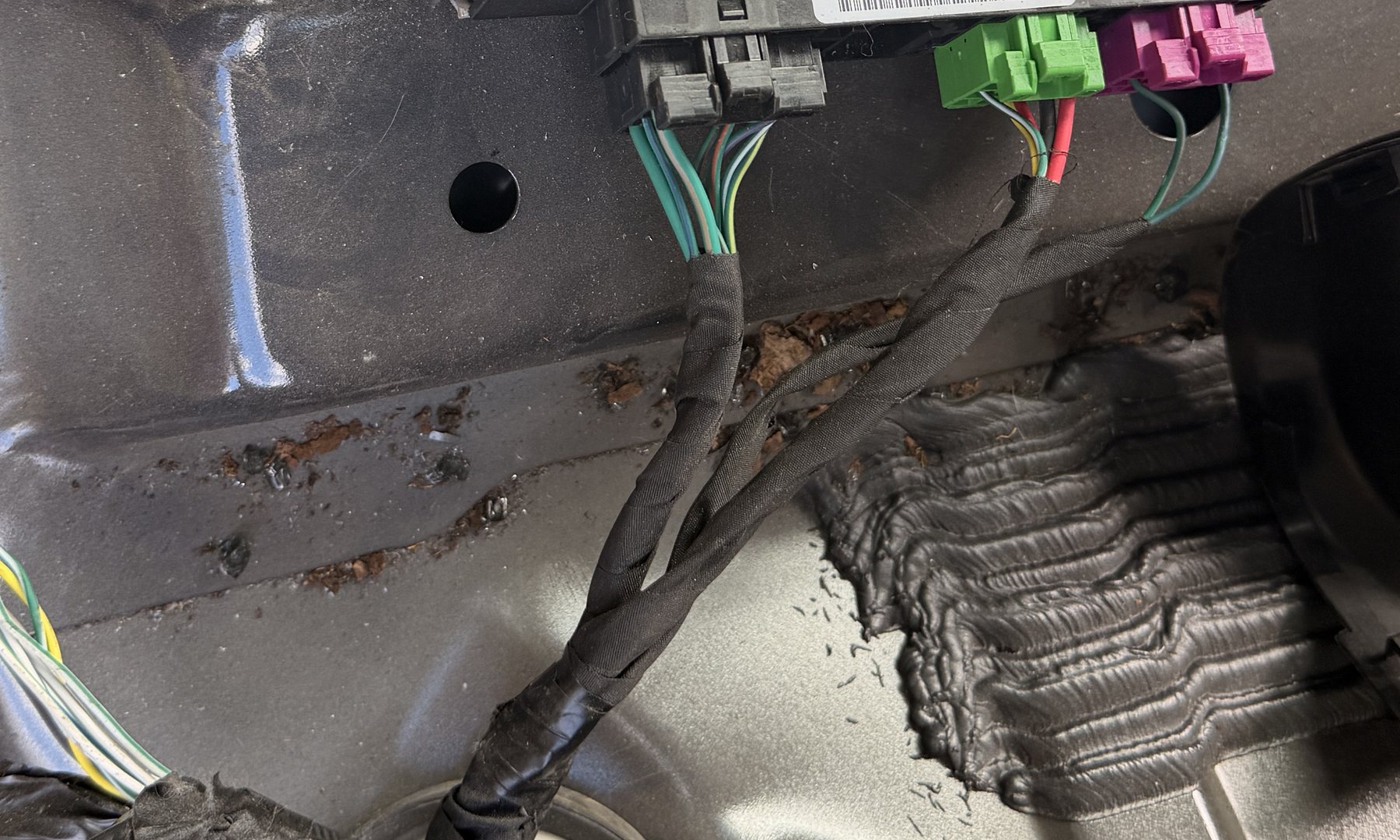
There is an electronic module tub under the driver’s seat that already holds the active damping module, the air suspension module and the DTCM. It has mounting rails in it — and the eLSD module slid straight onto a free pair as though it had been designed to go there.
It may well have been. Two things point that way. FCA runs these tubs as a shared multi-module bay, and the modules that live in it are the same Bosch physical form factor. And on the circuit diagrams the eLSD’s 20A always-hot feed is spliced off the same fuse as the air suspension module — PDC fuse F50, circuit A206. Those two systems are already related in the electrical design. A tub sized for one is sized for the other.
Whatever the reason, on a car without air suspension there is an empty, correctly sized slot sitting there.
One warning if you do this. That tub is busy. Any non-matching connector you find in it belongs to the DTCM or air suspension harness — leave it alone. Mounting in there is fine; cutting in there is not.
The relocation turned out to be the right call for more than convenience:
| Factory position | Module tub | |
|---|---|---|
| CAN tap | run to the IP star connector | inches from the DTCM |
| Run/Start feed | run forward from the PDC | F77 is the DTCM’s own fuse |
| B(+) from battery | front-to-rear run | short cross-car run |
| Differential harness | short | longer by a couple of feet |
Three of the four runs get shorter and simpler. The diff-side branch is the one that grows, and it is the branch you are building from scratch anyway.
It also explains why the DTCM was the obvious CAN tap. When the module you need to talk to is six inches away and already on the bus, you don’t go looking for the star connector.
Mounting hardware is 7 N·m, about 5 ft-lb. On this car the battery lives under the front passenger seat, so the heavy B(+) run ended up far shorter than planned.
Programming
Physical installation isn’t enough. The car has to be told the feature exists.
Back up the proxi configuration first. Then enable the eLSD / Quadra-Drive II configuration, run proxi alignment, and clear codes. I used JScan; AlfaOBD does the same job. Neither is a dealer tool and both are inexpensive.
With the configuration written, the scan tool could talk to the new module directly. From there:
- eLSD function test
- Quick Learn
- Verification and a test drive
Once the diff-side harness was actually correct, that was it.
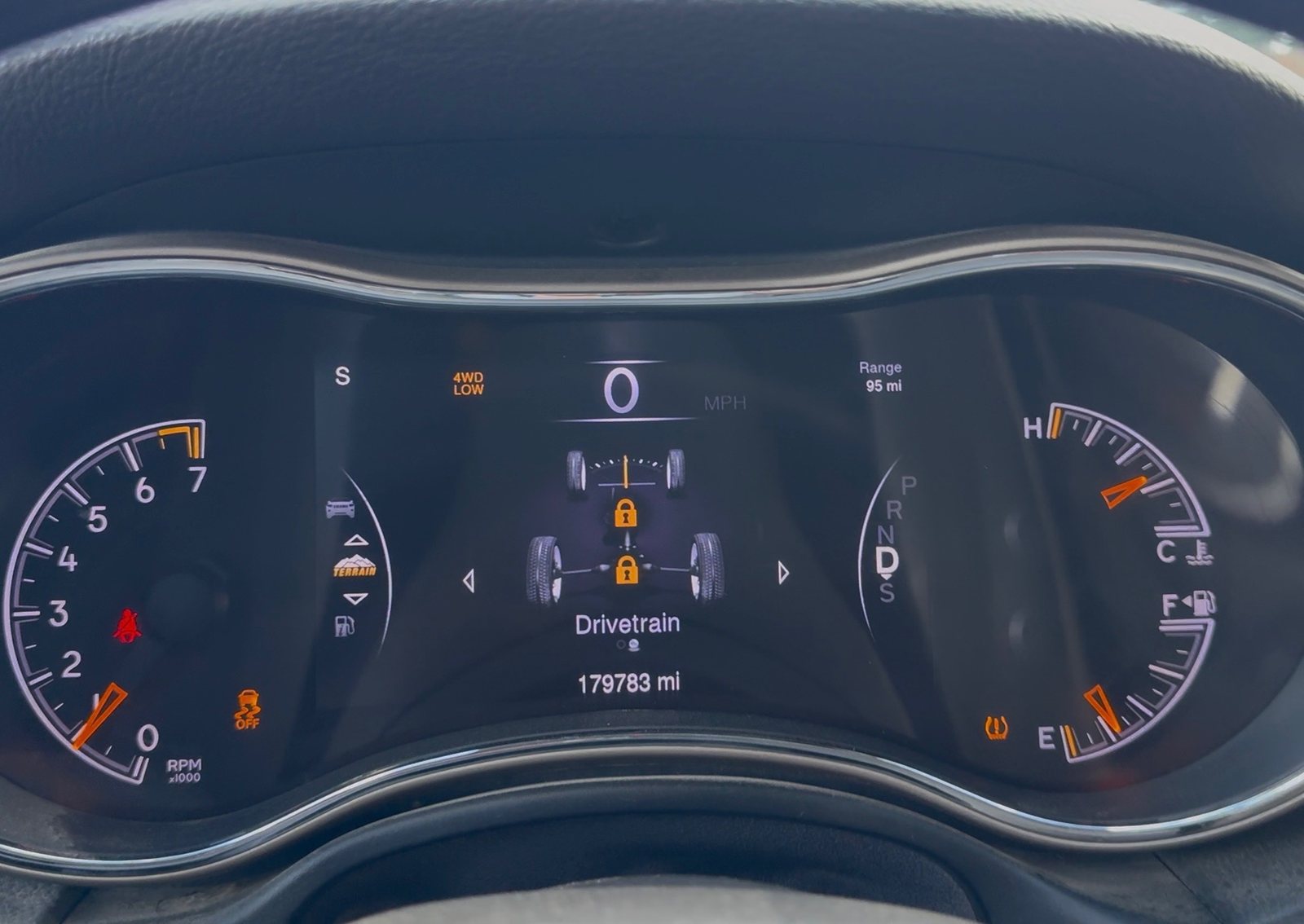
That second padlock is the whole project in one frame. The graphic was always in the software; it had nothing to display because the vehicle was configured as though the hardware didn’t exist.
Why this works at all
The thing that looks implausible about this job is the CAN connection. Two wires, spliced into the back of another module’s connector, and the new module simply appears.
But CAN is a shared bus. Modules hang off the same pair in parallel. The eLSD controller doesn’t need a private line to the ABS module or the PCM — it needs access to the network those modules are already talking on. Once it’s there, it listens for what it needs and transmits its own messages.
That’s also why the proxi configuration matters. The hardware works the moment it’s wired. The vehicle has to be told to expect it, or nothing goes looking for its messages.
The broader lesson is about how modular these platforms actually are. Manufacturers build many configurations on one electrical architecture, and features that look deeply integrated are often the hardware plus power plus network access plus a configuration flag.
That doesn’t make every factory option plug-and-play. But it does mean a parts catalog underestimates what’s possible.
Was it worth it
For an off-road Grand Cherokee, yes.
The factory eLSD stays integrated with Selec-Terrain and the existing traction systems. No aftermarket locker, no standalone controller, no separate switch to remember. It behaves like a factory feature because it is one.
The Jeep doesn’t know it didn’t leave Detroit this way. As far as the network is concerned, a module showed up where one was always expected to be able to.
If you’re going to try this
- Get the right-generation service manual. For a 2014+ car, a 2011 diagram is wrong in every field that matters. This was the single largest source of error in the whole project.
- Identify the diff-side conductors electrically, not visually. All ten are dark green and differ only by tracer. Motor windings read 1–5 Ω, the temp sensor 2–10 kΩ, the hall sensors not at all. That is a positive ID without reading a single stripe.
- Label physically as you map. Tape and a marker, before anything is cut.
- Map C1-1 and C1-3 first. The main motor pair, tan versus light green. Reversed, the actuator drives backward.
- Measure the bus too. 60 Ω across the CAN pair, key off — and note that the DTCM’s colours are inverted relative to the module’s.
- Photograph everything on the donor before it comes apart. Connectors latched, connector faces, wire color per cavity, bracket orientation.
- Look in the module tub under the driver’s seat before you commit to a location. There may already be an empty rail slot the right size, six inches from the DTCM.
- Fuse at the source, within a foot of the battery post.
- Back up the proxi config before you write to it.
Written up from our own build on a 2015 Grand Cherokee Limited. Figures and specs were verified against the FCA service manual for this generation; part numbers against Mopar catalog fitment data. Your car is not our car — check everything against documentation for your specific year before you cut into a harness. Modifying drivetrain wiring can damage modules that cost more than the part you’re fitting.